hforsten
@hforsten.com
340 followers
51 following
72 posts
Electrical engineer. RF electronics, IC design, radars, FPGA, programming. hforsten.com
Posts
Media
Videos
Starter Packs

hforsten
@hforsten.com
· 16m
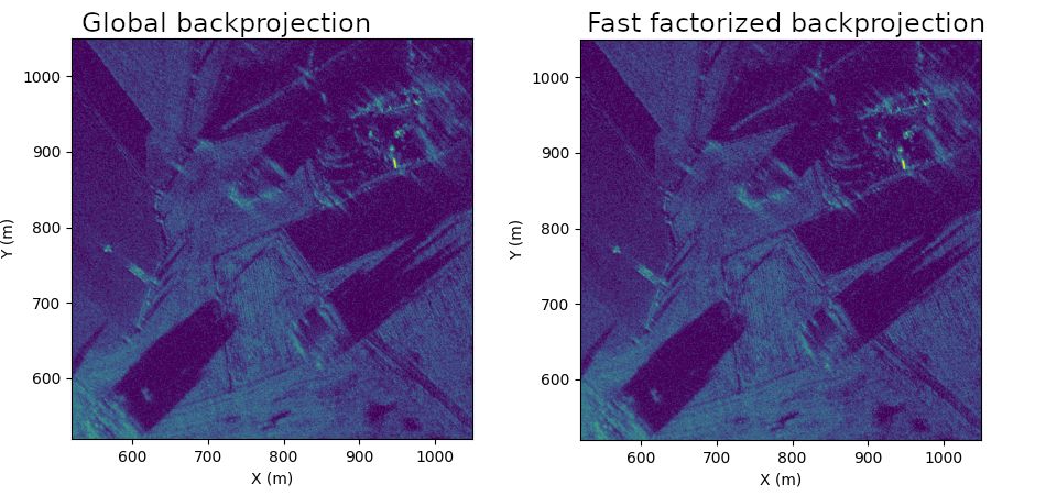
GitHub - Ttl/torchbp: Fast C++ Pytorch extension for differentiable synthetic aperture radar image formation and autofocus library on CPU and GPU
Fast C++ Pytorch extension for differentiable synthetic aperture radar image formation and autofocus library on CPU and GPU - Ttl/torchbp
github.com

hforsten
@hforsten.com
· 3d
hforsten
@hforsten.com
· Jun 12

hforsten
@hforsten.com
· Jun 1

hforsten
@hforsten.com
· May 30
hforsten
@hforsten.com
· May 29


hforsten
@hforsten.com
· May 15

hforsten
@hforsten.com
· Apr 15


hforsten
@hforsten.com
· Apr 5
hforsten
@hforsten.com
· Apr 5