Ken Shirriff
@righto.com
5.6K followers 290 following 330 posts
Computer history. Reverse-engineering old chips. Restored Apollo Guidance Computer, Alto. Ex-Google, Sun, Msft. So-called boffin.
Posts Media Videos Starter Packs
righto.com
If you want to know more about the IBM 1403 printer, I wrote about how we played music on it:
www.righto.com/2019/09/risk...
I also made an animation to explain the extraordinarily complicated timing between the hammers and the chain to print characters: static.righto.com/ibm1401/prin...
Risky line printer music on a vintage IBM mainframe
At the Computer History Museum , we recently obtained card decks for a 50-year-old computer music program. Back then, most computers didn't...
www.righto.com
righto.com
The hammers looked okay, but @tubetime.bsky.social found that hammer #83 was sticky. He cleaned it and then the printer worked, just in time for the demo. (Stop by the museum on Wednesdays or Saturdays to see the system in operation.) Photo shows a hammer from an earlier repair.
A hammer assemblly with the coil attached. It is an irregularly-shaped metal unit that is kind of grungy. It looks vaguely like an elephant with a long, straight trunk forming the part that hits the paper.
righto.com
We took the hammer unit out of the printer. Fortunately, IBM designed the printer for (relatively) easy maintenance. Inside the printer are two rails that can be attached to the back. The hammer unit slides out and tilts for access. You can see some hammers and coils; more are underneath.
The back side of the printer after removing the cover, paper guides, and cooling air hose. The hammer unit is a big gray unit in the middle. On either side, metal guide rails have been attached to the printer and stick out horizontally. The hammer unit has been slid out along the guide rails and tilted up. With the cover removed, you can see 33 electromagnetic coils in a row with a jumble of wiring behind. Each coil has a hammer, a gray rectangle of metal. At the bottom of the photo is a row of 132 small rectangles. These are the ends of the hammer that hit the paper to print characters.
righto.com
The line printer uses a chain with raised characters that spins at high speed. It has 132 hammers, one for each column. When the right character on the chain is in front of a hammer, the hammer fires, printing that character. But if a hammer fails, that column doesn't print, as you can see. 2/N
The print chain unit, about 14 inches wide and maybe an inch high. A chain is visible at the front with a sequence of raised charcters in reverse. An output page from the printer, displaying successive powers of two. One column stops printing partway down the page, with the failures circled in red ink. "Column 82" is written on the page, but it turns out that column 83 is the bad column.
righto.com
We fixed the vintage IBM printer at the Computer History Museum yesterday. Introduced in 1959, the IBM 1403 line printer provided fast, high-quality output, printing 132 character lines. Unfortunately, one column stopped printing, so we disassembled the printer to fix a bad hammer. Keep reading...
The IBM 1403 line printer is a large unit on a stand, printing on green-bar paper that feeds in at the bottom. The printer is dark gray with a clear plastic cover over the printer and a blue panel at the left with a few control buttons. Behind the printer, three 729 tape drives are visible, each about the size of a refrigerator. The IBM 1401 computer is partially visible at the right, about the size of two refrigerators. It has a control panel with lights, switches, and knobs.
righto.com
The regular repeating features are probably blocks of cache RAM.
righto.com
The iPhone 17 is powered by Apple's A19 SoC (System on a Chip). Chipwise took a die photo of the chip, but it's a bit drab. I spiced it up by applying the over-saturated color gradient that Apple used for die photos of the M1 chip :-)

Link to the original die photo: chipwise.tech/our-portfoli...
A complex die photo with many rectangular and irregular regions. I've applied a color gradient making the photo look slightly rainbow-ish, purple and blue in the top and red and yellow at the bottom. The image has a Chipwise logo on it.
righto.com
Marilou Schultz's rug is on display at SITE Santa Fe's current exhibition: "Once Within a Time"; let me know if you see it!

Photo credit: rug photo from First American Art Magazine (@firstamart.bsky.social‬).
righto.com
If you want to learn more about Marilou Schultz's amazing Pentium Navajo weaving, see my earlier thread:
bsky.app/profile/righ...
righto.com
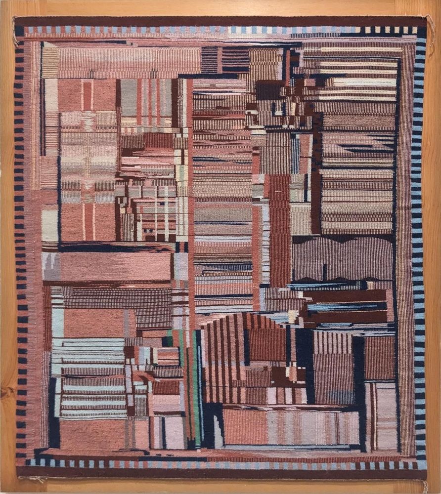
I recently saw an amazing Navajo rug at the National Gallery of Art. It looks abstract at first, but it is a detailed representation of the Intel Pentium processor. Called "Replica of a Chip", it was created in 1994 by Marilou Schultz, a Navajo/Diné weaver and math teacher. 1/n
A Navajo rug with a complex pattern with muted reds, pinks and blues. The pattern consists of various vertical and horizontal rectangles with stripes. Around the border are small alternating black and colored rectangles. The weaving is mounted in a wooden frame and hanging on the museum wall.
righto.com
Marilou Schultz first made a chip rug in 1994, when Intel commissioned a rug based on the Pentium as a gift to AISES (American Indian Science & Engineering Society). The Pentium weaving used natural dyes, while the 555 weaving uses aniline dyes and some metallic threads for more intense colors.
A rug representing the Intel Pentium processor. The style of this rug is very different from the previous one. It is a Navajo rug with a complex pattern with muted reds, pinks and blues. The pattern consists of various vertical and horizontal rectangles with stripes. Around the border are small alternating black and colored rectangles. The weaving is mounted in a wooden frame and hanging on the museum wall.
righto.com
Marilou Schultz based the rug on a photo by Antoine Bercovici (Siliconinsider). He used a special dark field microscope that produces a black background, highlighting the metal wiring on top of the silicon. The rug (left) mostly matches the photo (right), but there are some artistic changes.
An image of the rug next to a photograph of the 555 chip's die. Both are white patterns on a black background. They match closely, but there are a few changes. The wiring at the top has been simplified. The part number at the bottom has been removed.
righto.com
Here's a photo of the silicon die of the 555 chip—it's packaged in a metal can, rather than usual plastic rectangle, with 8 pins in a circle. If you zoom way in, you can see the pattern on the silicon matches the rug, in particular, the three large squares with a 王 pattern.
An integrated circuit in a metal can, sitting on top of a penny. I cut the top off the metal can, revealing the silicon die inside. The silicon die itself is a bit bigger than Lincoln's nose. Eight tiny bond wires connect the silicon die to the eight pins around the periphery of the metal can.
righto.com
Celebrated Navajo (Diné) artist Marilou Schultz recently completed a striking weaving. Although this rug may appear abstract, it is a representation of the wiring inside an integrated circuit. It shows the 555 timer, said at one point to be the world's most popular IC. Let's take a closer look...
A Navajo weaving hanging on a wall. The pattern appears abstract: thick white lines in varying directions on a black background. There are some reddish-orange diamonds near the edges, as well as a few thin outlined rectangles. There are three larger squares with a double-H pattern inside. Overall, the pattern looks a bit like an aerial view of roads in a strange ancient city. Thanks to First American Art Magazine for this photo.
righto.com
What do you mean? Let serves are a common thing.
righto.com
The first chip is the Fairchild 9040 flip-flop, which was manufactured by Navajo workers at the Fairchild's facility in Shiprock, NM. The second chip is the famous 555 timer. The weaving is based on a photo by Antoine Bercovici (Siliconinsider) that I suggested to the artist.
righto.com
The latest issue of @science.org mentions a magnetic compound Cr2Gr2Te6. The element Gr confused me, but it turned out to be a typo for Ge, germanium. Strangely, I found multiple papers with the same typo in the same context, so I wrote a short blog post about it.
www.righto.com/2025/08/Cr2G...
Text from the journal Science. I've highlighted the formula Cr2Gr2Te6; the rest of the text is not particularly relevant, discussing thin magnetic materials.
righto.com
Very nice! The author's name is Schultz, not Schulz, by the way.
righto.com
A few pins on the 386 have pull-up loads, e.g. so the pin has the right value if you don't have a floating-point coprocessor. These are different from the pull-up loads in NMOS chips like the 8086, where the load is a fundamental part of each gate.
righto.com
And if you're interested in the 386, you should check out my previous thread on the 386's packaging, which has some neat 3-D CT scan images:
bsky.app/profile/did:...
righto.com
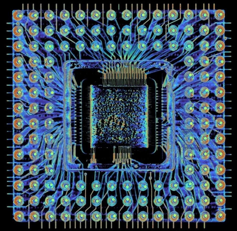
Intel's 386 processor was popular in late 1980s microcomputers. From the outside, the 386 chip is a boring ceramic square. But I obtained a 3-dimensional CT X-ray scan from Lumafield, revealing six layers of complex wiring hidden inside the ceramic package. Let's take a closer look... 1/N
An X-ray scan of the 386 chip. It shows a square with a grid of 132 pins. In the middle is a square, the silicon die. Blue wires connect the pins to the chip. Spikes stick out all around the perimeter of the package.
righto.com
The 386 uses a complicated circuit, based on a memory chip's "sense amplifier" to reduce metastability. The sense amplifier speeds up the decision between 0 and 1. This circuit is relatively large, so only a few pins need it, inputs with unpredictable timings.
Another close-up die photo. This one shows more circuitry than the previous ones. It shows two standard latch circuits, along with two special sense-amplifier latch circuits that reduce metastability. The sense-amp latch circuits are larger than the regular latches. The diagram also shows protection diodes and guard rings. At the bottom, the large square bond pad is where the bond wire is attached. A schematic with a bunch of transistors. At the top are two latches, active in the first clock phase. At the bottom is the sense amplifier, active in the second clock phase. The sense amplifier has cross-coupled transistors, similar to cross-coupled inverters. But it also has similarities with a differential amplifier.