


Martin Donlon
@wickerwaka.com
Professional game developer. Unprofessional FPGA developer, hardware hacker and reverse engineer.
When I saw video from an arcade PCB I guessed that the shimmer was something do with what I called "spooky" sprites which is something I encountered when I made some tests for sprite positioning and scaling. I ignored it at the time because I hadn't seen any games use it.
October 12, 2025 at 3:31 PM
When I saw video from an arcade PCB I guessed that the shimmer was something do with what I called "spooky" sprites which is something I encountered when I made some tests for sprite positioning and scaling. I ignored it at the time because I hadn't seen any games use it.
The latest version of the Taito F2 core fixes the shadows in PuLiRuLa so they "shimmer" like you see in the video. The shadows are just the character sprites drawn with a black color palette and scaled down vertically. So what makes them shimmer?
October 12, 2025 at 3:31 PM
The latest version of the Taito F2 core fixes the shadows in PuLiRuLa so they "shimmer" like you see in the video. The shadows are just the character sprites drawn with a black color palette and scaled down vertically. So what makes them shimmer?
I've sold out of PicoROMs. I made 150 and sold 130. I'm surprised I managed to sell so many because I think it's pretty niche. I've no idea what people are using them for, so if you bought some and you are using them, please let me know!
August 1, 2025 at 4:07 PM
I've sold out of PicoROMs. I made 150 and sold 130. I'm surprised I managed to sell so many because I think it's pretty niche. I've no idea what people are using them for, so if you bought some and you are using them, please let me know!
The end result was pretty easy to replicate in the core. Of course I haven't found a single game that actually uses this functionality. Maybe something will come up, but even if it doesn't it's nice to uncover more secrets.
June 16, 2025 at 3:17 AM
The end result was pretty easy to replicate in the core. Of course I haven't found a single game that actually uses this functionality. Maybe something will come up, but even if it doesn't it's nice to uncover more secrets.
The TC0360PRI is used in the Taito F2 and several other boards. I prioritizes/mixes up to 3 12-bit color inputs. It has a few different "blend" modes for combining the inputs and some flags for those modes. I built a little test screen so I could test all the different parameters on real hardware.
June 16, 2025 at 3:17 AM
The TC0360PRI is used in the Taito F2 and several other boards. I prioritizes/mixes up to 3 12-bit color inputs. It has a few different "blend" modes for combining the inputs and some flags for those modes. I built a little test screen so I could test all the different parameters on real hardware.
It turns out the exact same chip is used by Taito in some of their NES games. Not sure what came first, but it looks to me like they decided to shoe horn this into their F2 boards because it generally did what they needed.

May 11, 2025 at 10:46 PM
It turns out the exact same chip is used by Taito in some of their NES games. Not sure what came first, but it looks to me like they decided to shoe horn this into their F2 boards because it generally did what they needed.
This chip is very out of place on the F2 boards. It’s the only custom chip using DIP form factor and the logo is different than all the other ones. It is used to expand the amount of tile graphics available.

May 11, 2025 at 10:46 PM
This chip is very out of place on the F2 boards. It’s the only custom chip using DIP form factor and the logo is different than all the other ones. It is used to expand the amount of tile graphics available.
Using MDFourier results I tweaked the values a little bit further to get something that matched more closely. Everything is within 3dB of the original hardware and the relative volumes of the PSG and FM data.

April 30, 2025 at 9:05 PM
Using MDFourier results I tweaked the values a little bit further to get something that matched more closely. Everything is within 3dB of the original hardware and the relative volumes of the PSG and FM data.
Aurally speaking, the FM would have sounded "tinnier." On the board the FM audio goes through a series of low pass filters. I have the Final Blow schematics, but instead of analyzing it myself I decided to ask ChatGPT. I gave it this image and asked, "What does this do?"

April 30, 2025 at 9:05 PM
Aurally speaking, the FM would have sounded "tinnier." On the board the FM audio goes through a series of low pass filters. I have the Final Blow schematics, but instead of analyzing it myself I decided to ask ChatGPT. I gave it this image and asked, "What does this do?"
The yellow line is PSG audio from the YM2610, this matches pretty closely because it has no filtering on the board. The slight differences are due to the power amp (and maybe the supergun). The green line is the FM audio, which does have filtering and you can see larger differences on the high end.

April 30, 2025 at 9:05 PM
The yellow line is PSG audio from the YM2610, this matches pretty closely because it has no filtering on the board. The slight differences are due to the power amp (and maybe the supergun). The green line is the FM audio, which does have filtering and you can see larger differences on the high end.
What does it sound like? Amazing. All the beep, bloops and csssschks you could hope for. I captured this audio through the supergun and ran the same test on the core on the DE-10 and captured it's output using a HDMI capture device, then compared them using MDFourier.
April 30, 2025 at 9:05 PM
What does it sound like? Amazing. All the beep, bloops and csssschks you could hope for. I captured this audio through the supergun and ran the same test on the core on the DE-10 and captured it's output using a HDMI capture device, then compared them using MDFourier.
To do this I needed to output an audio test pattern. I was able to port this from the Neo Geo 240p Test Suite pretty easily. Just needed to adapt addresses and ports. Luckily, since PicoROMs can be powered over USB, they can work as 28-pin ROMs as long as you have the space.

April 30, 2025 at 9:05 PM
To do this I needed to output an audio test pattern. I was able to port this from the Neo Geo 240p Test Suite pretty easily. Just needed to adapt addresses and ports. Luckily, since PicoROMs can be powered over USB, they can work as 28-pin ROMs as long as you have the space.
Having your own code running on hardware and the simulator allows narrow it down to the bare essentials. Really useful when you just want to see that first image on screen to keep yourself motivated.
April 6, 2025 at 6:20 PM
Having your own code running on hardware and the simulator allows narrow it down to the bare essentials. Really useful when you just want to see that first image on screen to keep yourself motivated.
I damaged a Final Blow board almost two years ago and that's what motivated me to develop the PicoROM. I used it through out development to build small isolated test cases that I could run on real hardware and in the simulator and compare the results.
April 6, 2025 at 6:20 PM
I damaged a Final Blow board almost two years ago and that's what motivated me to develop the PicoROM. I used it through out development to build small isolated test cases that I could run on real hardware and in the simulator and compare the results.
Robert Peip uses save states extensively so I knew they would be useful, but I never appreciated just how useful. Simulation is slow, about 1fps, so being able to jump to a particular point in time is a huge time saving. Being able to save a state on the DE-10 and load it in the sim is massive!
April 6, 2025 at 6:20 PM
Robert Peip uses save states extensively so I knew they would be useful, but I never appreciated just how useful. Simulation is slow, about 1fps, so being able to jump to a particular point in time is a huge time saving. Being able to save a state on the DE-10 and load it in the sim is massive!
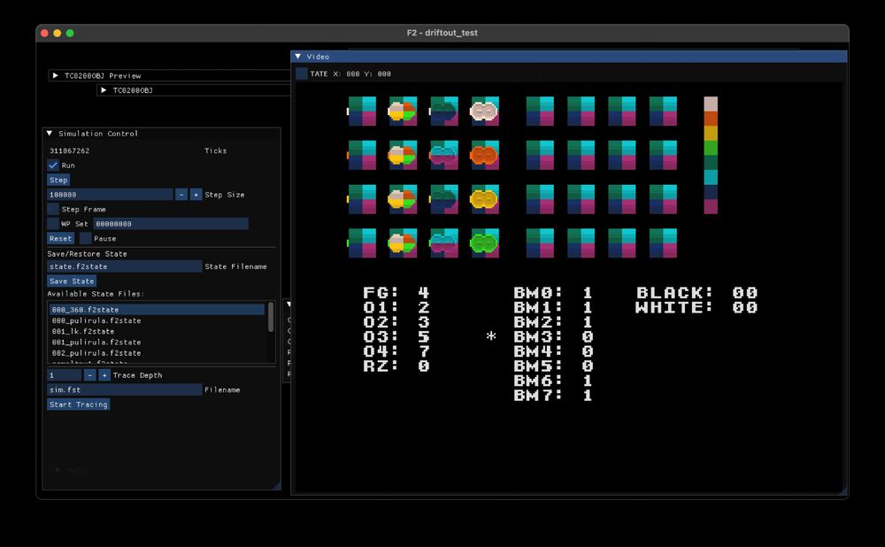
Maybe most important of all it allows me to work on my laptop, which is where I did 90% of the development. I built this sprite memory viewer while on a flight and I implemented most of the sprite system while on vacation.

April 6, 2025 at 6:20 PM
Maybe most important of all it allows me to work on my laptop, which is where I did 90% of the development. I built this sprite memory viewer while on a flight and I implemented most of the sprite system while on vacation.
I took inspiration from @mrjimmystones.bsky.social and built my own verilator-based simulator. This allows for significantly faster compile times, 10 seconds vs 13 minutes. It makes it possible to trace the entire state of the system at any time.
April 6, 2025 at 6:20 PM
I took inspiration from @mrjimmystones.bsky.social and built my own verilator-based simulator. This allows for significantly faster compile times, 10 seconds vs 13 minutes. It makes it possible to trace the entire state of the system at any time.
A month ago I started working on an FPGA core for Taito's Final Blow, the first game on their F2 arcade system. Yesterday I had it running on the #MiSTerFPGA with all major systems in place. Lots of bugs left to fix, but the hardest parts are done.
April 6, 2025 at 6:20 PM
A month ago I started working on an FPGA core for Taito's Final Blow, the first game on their F2 arcade system. Yesterday I had it running on the #MiSTerFPGA with all major systems in place. Lots of bugs left to fix, but the hardest parts are done.

She’s 8,000 miles away, working her butt off and still finds time to show her love. She is the greatest gift.

March 2, 2025 at 3:20 PM
She’s 8,000 miles away, working her butt off and still finds time to show her love. She is the greatest gift.
I like that Windows Terminal includes this font preview. But no uppercase 'I' or 'O' and no 0 (zero)?!

February 10, 2025 at 7:23 PM
I like that Windows Terminal includes this font preview. But no uppercase 'I' or 'O' and no 0 (zero)?!
So I decided to make some adaptors that would allow me to connect these CPUs directly to a DE-10 Nano. With these I should be able to both drive and analyze the CPU behavior without any additional hardware.

January 20, 2025 at 4:51 PM
So I decided to make some adaptors that would allow me to connect these CPUs directly to a DE-10 Nano. With these I should be able to both drive and analyze the CPU behavior without any additional hardware.
Since the beginning I've been analyzing CPU behavior directly on arcade boards. It's convenient because it's already there and working, but hooking up probes is time consuming and fragile. Plus you are limited by what signals are used by the arcade board.

January 20, 2025 at 4:51 PM
Since the beginning I've been analyzing CPU behavior directly on arcade boards. It's convenient because it's already there and working, but hooking up probes is time consuming and fragile. Plus you are limited by what signals are used by the arcade board.
The amount of CAD/CAM accessible to any idiot these days is fascinating. I was having trouble soldering this single pin neatly. So I used the amazing 3d model that my *free* PCB design software created to design a jig and 3D printed it. Went through 3 iterations on a Friday evening.


December 14, 2024 at 3:42 PM
The amount of CAD/CAM accessible to any idiot these days is fascinating. I was having trouble soldering this single pin neatly. So I used the amazing 3d model that my *free* PCB design software created to design a jig and 3D printed it. Went through 3 iterations on a Friday evening.
I've never used PC manipulation or sideset on the RP2040 PIO before. Two days ago while watching a music recital at my kids school I realized I could use it to do a really fast OR. It could be used for any kind of LUT with up to 5 inputs and outputs.

December 13, 2024 at 5:31 AM
I've never used PC manipulation or sideset on the RP2040 PIO before. Two days ago while watching a music recital at my kids school I realized I could use it to do a really fast OR. It could be used for any kind of LUT with up to 5 inputs and outputs.