Mark J. Koch
@markjkoch.bsky.social
230 followers 310 following 98 posts
Retired Digital Alchemist. Cyber Monk. Technologist. Containment Specialist at -redacted-. Sun Microsystems Labs Alumni. Former SFX specialist at Blue Man Group. Hobbies: Game Design in Java/JavaFX, Analog Synth, PCB design, Robots, Gardening, Cooking.
Posts Media Videos Starter Packs
markjkoch.bsky.social
A nice way to end the week! Got my #synth module working. Based on an open source design by Hagiwo. #RasPi #Pico2 based and using Arduino libraries, generates waves from tables or math. I added OLED and UI code. I think the PCB components need work as the output looks a little funky. #asmr-synth
markjkoch.bsky.social
All I see is Arthur Dent and Zaphod Beeblebrox. #hhgtg #douglasadams #hitchhikersguidetothegalaxy #thehitchhikersguidetothegalaxy #towelday #dontpanic #scifi
markjkoch.bsky.social
#synth rack progress! One regulator wouldn't start up, so it took a deeper read into the data sheet to realize I'd missed some components needed for voltages above 5V (a zener and cap). #Zener ended up being a stack of Zeners to achieve desired value. Not my prettiest fix. #pcb #kicad #electronics
My quad output power supply for my Eurorack alternative idea.  Many engineers don't know it but you can make a typical buck regulator put out negative voltage if you swap the ground and Vout lines.  The Vout is grounded and the common lines inside the circuit will output a negative potential of the desired output voltage.  Feels unintuitive when designing, but works well.  Also, this design uses the HUSB power negotiation chip to allow the board to be powered with a USB-PD capable laptop supply.  Using the HUSB chip, those supplies can negotiate a range of output voltages like 5, 9, 12, 18 and 20V at 3 or more amperes. I'm using 20V in this design to then generate the +15, -15 and 5V needed for analog synthesizer circuits. This bodge is the missing Zener.  I needed a zener of around 11.5V but only had some 3.2V laying around. So I hooked four SOT023 type in series to get close to the value I wanted.  Kicking myself for not studying the data sheet more at design time. It's right there. The data sheet for this buck regulator shows that for output voltages above 12V, a zener is needed to bring the boost voltage into proper range.  Once I did this, the whole thing just worked.
markjkoch.bsky.social
I don’t have a #Mouser parts purchasing problem! I can stop any time I want. #kicad #pcb #engineering
markjkoch.bsky.social
Upon finding this stainless steel bowl at #ikea that looks suspiciously like a half scale #R2D2 head…. Challenge accepted!
markjkoch.bsky.social
My #JLCPCB bounty included my prototype #PCB s for a new type of rack #synth that I am thinking about. Think #eurorack but dragged into the new millennium. Backplane has two #I2C busses, slot detection, and 32 negotiated patch signals. Slightly larger such that old ER modules can nest inside.
ASMR Synth Rack backplane, ten slot, featuring PCI-type edge connectors.  Not actually PCI.  Mine has four voltages, 18-24V, +15, -15 and 5V.  There's two I2C busses, slot detection and 32 undefined "patch" lines.  The inserted synth cards can negotiate the use of the patch lines for analog audio/control voltage and digital uses. Back plane can be up to 16 slots.  Currently working on a 100% 3D printable chassis design.   It will be 100% open source. ASMR two slot backplane for bench development purposes. Prototype ASMR hardware as received from the PCB fabrication service.  Bottom is 10 slot backplane. Bottom right is a two slot back plane. Center is three experimental boards: top is a breadboard experimenters board, middle is a power supply (USB-PD in, +/-15V and 5V out) and bottom is an implementation of Hagiwo's amazing MOD2 synth module ( I added a one inch OLED display). Right are two face plates for the rack system:   The breadboard PCB faceplate and the power supply faceplate. Example of how the ASMR cards plug into the backplane.  A rack chassis will be made soon to bring it all together.
markjkoch.bsky.social
Yay! The main #PCB for my MOS #KIM-1 replica arrived today from #JLCPCB! The sub-boards seem to fit. Bringup will take awhile since there's a gross chip-pin-numbering error on one of the smaller boards and I'll have to re-fab it. But I'll be able to partially assemble it and test a few things.
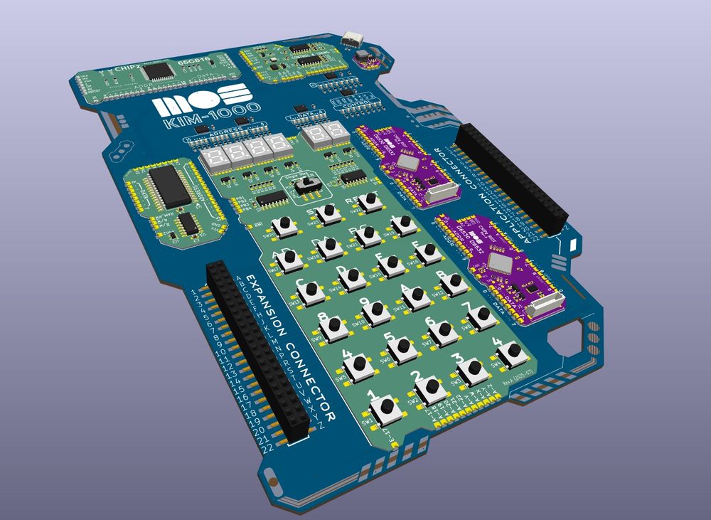
My KIM-1 replica, affectionately named "KIM-1000".  An all surface mount version based on the original 1970's schematic.  I attempted to add a Cyberpunk-ish style to the edges. My KIM-1 replica, affectionately named "KIM-1000".  An all surface mount version based on the original 1970's schematic.  I attempted to add a Cyberpunk-ish style to the edges.
markjkoch.bsky.social
When your latest #PCB uses a #PCI connector (super dirt cheap) and you want the customer to know that they should not even be tempted to plug it into a PC. I used the connector but the pinout and voltages are nowhere near those of PC Cards. At least the warning will be entertaining. #KiCAD
A Printed Circuit Board with what looks like a PCI connector edge. There is a warning imprinted onto the board that states, "Absolutely NOT PCI! Do NOT attempt to use in a computer. SMOKE, FIRE or SMELLS MAY OCCUR."
markjkoch.bsky.social
It's alive! Keypad/Display #PCB module for my #kim-1 replica is working! Mostly based on the original 1970s #schematic, using modern parts. I wrote a PCB test fixture using Arduino and #rp2040 #raspberrypipico module from #adafruit. My first time using a rp2040 was mostly painless. #65C02
markjkoch.bsky.social
Tracking the person delivering my #UPS package. This individual should get a job in professional gerrymandering. Has driven past my neighborhood twice already and returned to multiple places they were before. Package is also an hour after the original delivery window. This is performance art.
markjkoch.bsky.social
When a billionaire/celebrity/philanthropist looks at your profile on LinkedIn and you’re not sure if you should be elated or worried.
markjkoch.bsky.social
My #analytical brain, every time I touch something and get a #shock: "I've been sitting still for five minutes! Why am I loosing so many #electrons so quickly? Is there something I can do about it?" #zap
markjkoch.bsky.social
That #feeling you have when you do a #GIT commit before going to help a family member with something for almost six hours. My day is gone but ideas in my head are check-pointed. #codelife
markjkoch.bsky.social
This is a public service announcement for you to support your local PBS station! #PBS #RickSteves
World Traveller, Rick Steves, as a pickle!   Support your local PBS station to keep getting more Rick.
markjkoch.bsky.social
OK. Why not? SPOILER ALERT! ... Labeled as "Suggestive" to blur image for those who don't want to see it before it's a real thing.
KiVAD render of the MOS KIM-1000.  A modern take on the KIM-1 CPU board from the 1970's.   I really wanted one of the original KIM-1 boards as a kid but, being a kid, no money.  However, when I reached college, my degree included theory and hands on with our very own Z-80 systems that we got to build using raw components and wire wrap!  Worked the same as the KIM-1 and we even had to write our own operating program.  The following semester we got to expand our Z-80s with the peripheral of our choice.  I built a full robot that I'd already been working on since I was 14-ish.  I programmed it to work like the "Big Track" toy. I handed all my original documentation, schematics and code to the professor to get my grade (should have made some photocopies at least).  Never did get any of that back.  This was a couple years before things like floppy disks and ease of and access to printers.
markjkoch.bsky.social
Do I show the 3D render of the whole thing or do I make everyone wait for the final real system in a couple months?
markjkoch.bsky.social
Hey Johnson! You can always reach out to me for Arduino questions. Also, Adafruit website has many tutorials, products and code for doing the exactly kind of stuff you want to do.
markjkoch.bsky.social
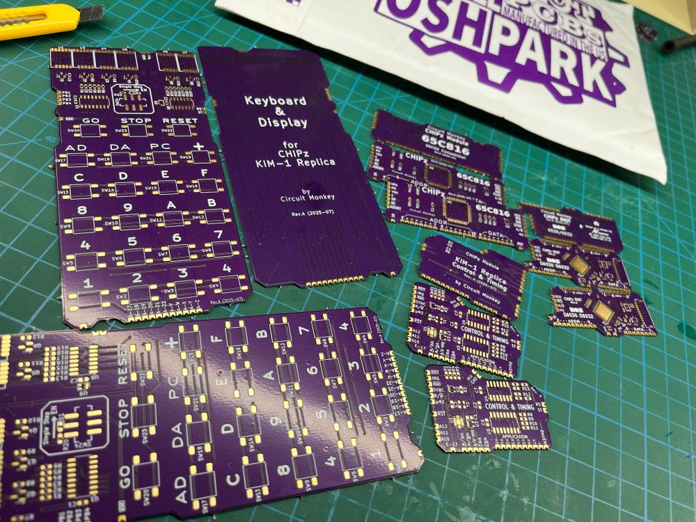
My @oshpark.bsky.social PCBs arrived. They are part of my #kicad project to create a #KIM-1 #65c02 computer replica, with a twist. I started with the original schematic but broke it into SMT modules. Each module is a castellated #PCB "stamp" for a larger main board that I'm finishing up.
markjkoch.bsky.social
If they ever reboot "Back to the Future", they should use the #CyberTruck. Except, on this new set of movies, to activate time travel, you'd have to rear-end the CyberTruck using a different vehicle at 88MPH. It would help add one more metaphor to the "Back" part of the name in the title.
Reposted by Mark J. Koch
spetku.bsky.social
Midsummer is upon us. May we all find something sticky and delicious to adorn our skin with this week🍉
#summer
An illustrated comic of three humans garbed in bed sheets and crowns made from long feather-like leaves. Arms outstretched in offering to the crescent moon, devoured watermelon rinds also in the same crescent shape. They celebrate the middle of summer by enjoying fruit.
markjkoch.bsky.social
Me repeatedly asking my partner if they want to go to Sushi: "I don't know. Maybe next week."
Me asking my partner once about attending a ham radio meetup: "Yes! Let's go!"
Someday little nigiri, some day soon.
markjkoch.bsky.social
I am so screwed…
egypturnash.bsky.social
Never trust anyone online whose icon appears to be a photograph of a human being.
markjkoch.bsky.social
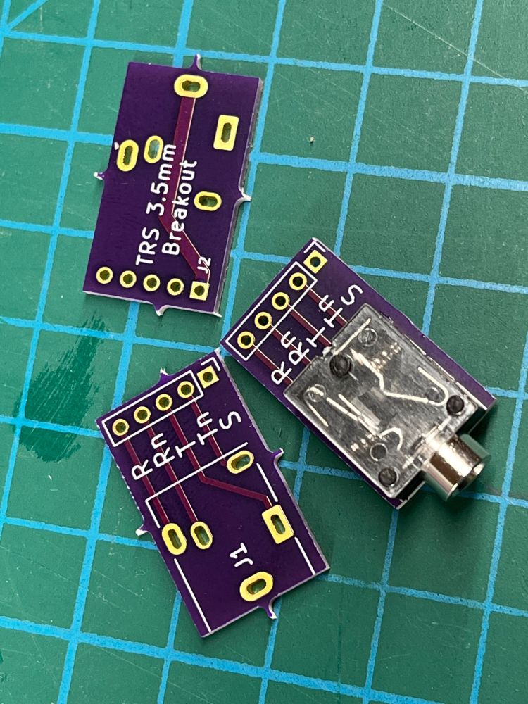
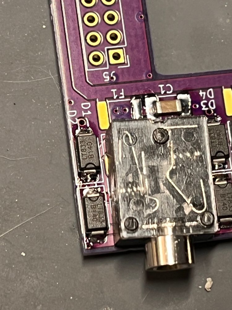
Ughhh! That 2 degree twist on the audio jack. Thanks #kicad! And thus I kick off the official open source version of my custom "tuned" KiCAD library. I can't be that harsh since #EagleCAD included libraries were full of this kind of anomalous shenanigans that gave me trust issues. #PCB
PCB showing the mounted TRS audio jack with a  slight 2 degree turn. It turns out that the KiCAD supplied library footprint has multiple inaccurate dimensions.
Reposted by Mark J. Koch
dphrygian.com
Engineers have opinions about coordinate spaces.
A young woman assisting an older woman with a walker.
Older woman: "Z is up"
Young woman: "Sure grandma"